Experiment 2: LED and buzzer with digital, PWM and ultrasonic control
One output stage (an LED and an active buzzer) driven by three different inputs. The real subject is encoding: a level, a PWM duty cycle, and a distance carried inside a pulse width.
Objective
- Part 1
- Switch an LED and an active buzzer together at 0.5 Hz with digital output.
- Part 2
- Make the LED brightness (and buzzer drive) follow a knob: analog input → scaled → PWM output.
- Part 3
- Measure distance with an HC-SR04 and turn the LED and buzzer on when an object is within 200 cm.
- Learn
- digital vs analog input, ADC resolution, PWM, range conversion with
map(), and time-of-flight measurement withpulseIn().
System
| Part | Input encoding | Transfer function in code | Output encoding |
|---|---|---|---|
| 1 | time (delay) | toggle every 1000 ms | level: HIGH/LOW |
| 2 | voltage → 10-bit ADC code 0 to 1023 | map(x, 0, 1023, 0, 255) | PWM duty 0 to 255 |
| 3 | pulse width in µs | distance = t / 2 × 0.0343, then distance <= 200 | level: HIGH/LOW |
Design decisions
Arduino MEGA instead of UNO
- Why
- More pins and 16 analog inputs; the code uses A7, which the UNO does not have.
- Alternative
- UNO with the pot on A0 to A5 and PWM pins chosen from 3, 5, 6, 9, 10, 11.
- Switch when
- When the pin count fits, the UNO is smaller and cheaper.
Active buzzer
- Why
- It contains its own oscillator, so plain
digitalWrite(HIGH)makes a tone. No timing code needed. - Alternative
- Passive buzzer driven by
tone(pin, freq). - Switch when
- When you need different pitches (the siren in Exp 3 needs a passive one).
10 kΩ potentiometer as a voltage divider
- Why
- Ends on 5 V and GND, wiper on the ADC: the wiper voltage is proportional to the shaft angle and the pot draws only 0.5 mA.
- Alternative
- A rotary encoder (digital, endless rotation) or buttons for up/down.
- Switch when
- Use an encoder when you need relative movement, no end stops, or no ADC noise.
Rescale with map()
- Why
- The ADC gives 0 to 1023 (10 bits) and
analogWrite()takes 0 to 255 (8 bits);map()states the conversion explicitly. - Alternative
readVal / 4orreadVal >> 2gives the same range with less arithmetic.- Switch when
- Bit shifting when speed matters;
map()when ranges are not powers of two.
HC-SR04 ultrasonic sensor
- Why
- Cheap, 2 to 400 cm range, works regardless of colour or ambient light, needs only two GPIOs and a timing function.
- Alternative
- IR distance sensor (analog, nonlinear, colour-sensitive) or a laser time-of-flight sensor such as VL53L0X (I²C, narrow beam, mm resolution).
- Switch when
- ToF for a narrow, precise measurement; IR for very short range; ultrasonic for cheap obstacle detection.
Measure the echo with pulseIn()
- Why
- One blocking call returns the pulse width in µs; no interrupt code.
- Alternative
- Interrupt on ECHO rising and falling edges, recording
micros()each time. - Switch when
- When the loop must not block for up to tens of milliseconds per reading.
Fixed 200 cm threshold, checked once per second
- Why
- The simplest decision rule; easy to verify in the simulator.
- Alternative
- Two thresholds (hysteresis), averaging several readings, or a smaller threshold such as 30 cm.
- Switch when
- Any real alarm, to stop flicker at the boundary and false triggers.
What we did
Part 1: wired LED to pin 2 and buzzer to pin 4, each via 220 Ω; uploaded the sketch; checked the greeting on the Serial Monitor.
Each load needs its own pin and its current limited. The greeting proves the sketch is running.
Part 2: pot ends to 5 V and GND, wiper to A7; LED to pin 7, buzzer to pin 9.
The ends define the 0 to 5 V span; pins 7 and 9 are PWM-capable on the MEGA, which
analogWrite()needs.Turned the knob while watching the Serial Monitor.
Printing raw and mapped values lets you verify the conversion by hand (163 → 40).
Part 3: HC-SR04 VCC to 5 V, GND, TRIG to pin 3, ECHO to A7; LED to 12, buzzer to 7.
TRIG is an output (we start a measurement); ECHO is an input (the sensor reports). Analog pins work as digital inputs.
Moved a hand or set the simulator distance, and compared printed distances with reality.
Checks the time-to-distance formula and the threshold.
Part 1: on/off control
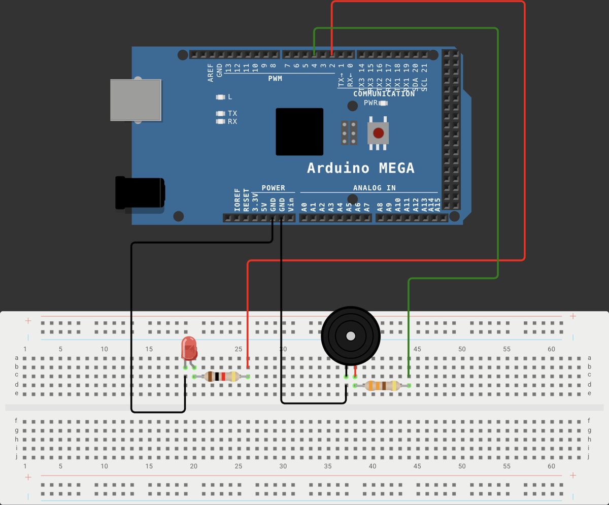
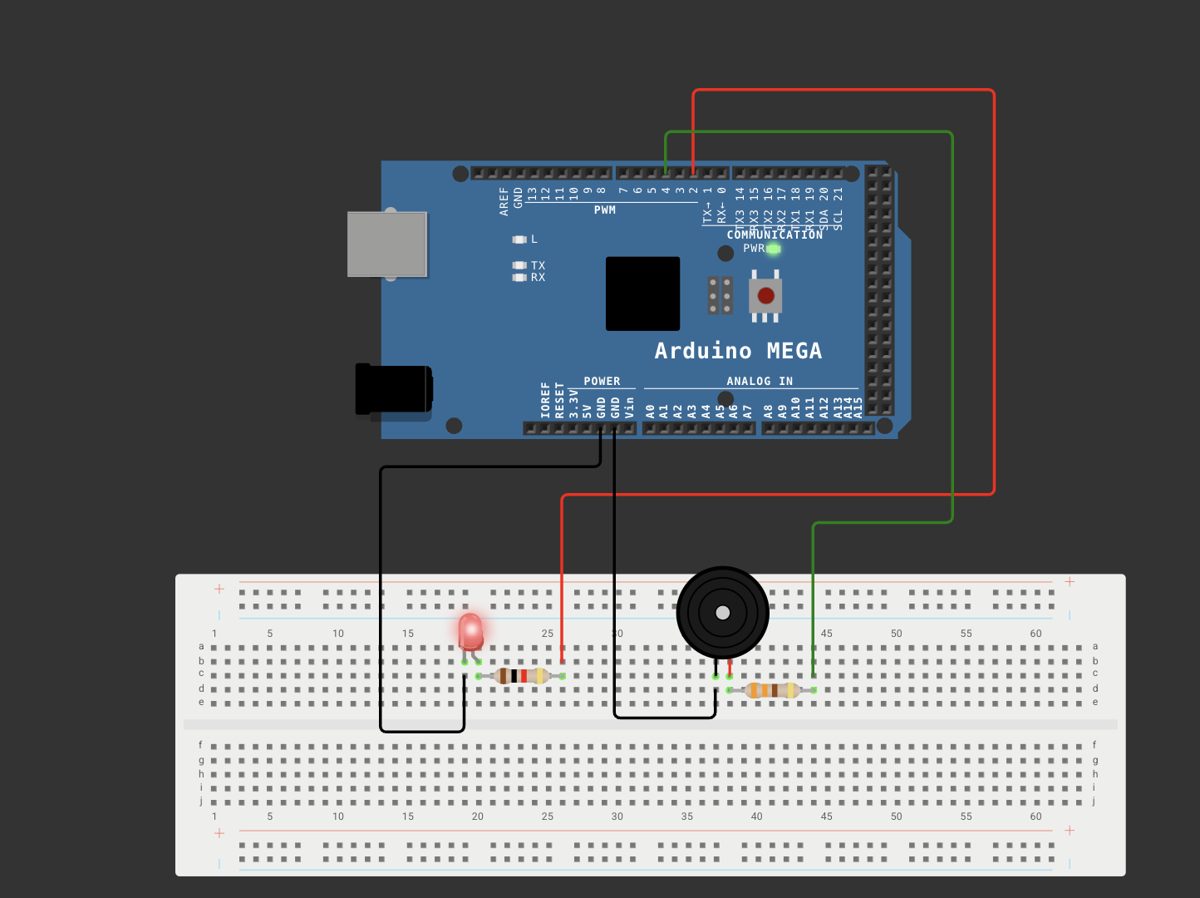
- Red wire from pin 2 to the LED branch, green wire from pin 4 to the buzzer branch (you can see both wires leave pins 2 and 4 on the header).
- Each branch has a resistor in series and returns to GND (black wires).
- Two independent outputs, written in the same pass, so they switch together.
Part 1: LED and buzzer
int ledPin = 2;int buzzPin = 4; void setup() { // put your setup code here, to run once: Serial.begin(9600); Serial.println("Hello Ardino!!"); pinMode(ledPin, OUTPUT); pinMode(buzzPin, OUTPUT);} void loop() { // put your main code here, to run repeatedly: digitalWrite(ledPin, HIGH); digitalWrite(buzzPin, HIGH); delay(1000); digitalWrite(ledPin, LOW); digitalWrite(buzzPin, LOW); delay(1000);}- Lines 1 to 2Two outputs.
- Lines 6 to 7Banner on start. The typo is inside a string literal and has no effect.
- Lines 9 to 10Both pins driven.
- Lines 15 to 17Both HIGH, hold 1 s. The active buzzer’s oscillator runs while powered.
- Lines 19 to 21Both LOW, hold 1 s. Period 2 s, 0.5 Hz.
Part 2: potentiometer to PWM
The chain is: angle → wiper voltage → ADC code (0 to 1023) → map() → duty (0 to 255) → average output voltage. map() computes (x − in_min) × (out_max − out_min) / (in_max − in_min) + out_min in integer arithmetic, so the fraction is truncated, not rounded.
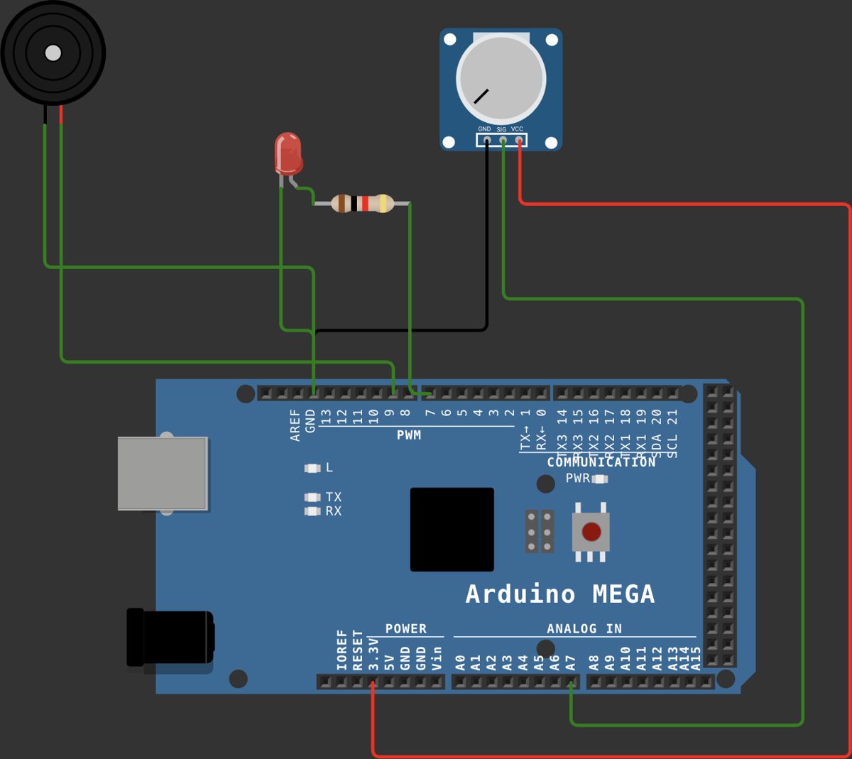
- Pot: red wire to 5 V, black to GND, green from the middle pin (wiper) to A7 on the analog header.
- LED (via resistor) and buzzer on the PWM header, pins 7 and 9.
Part 2: potentiometer
int ledPin = 7;int buzzPin = 9;int potPin = A7;int readVal;int mapVal; void setup() { // put your setup code here, to run once: Serial.begin(9600); Serial.print("HEllo"); pinMode(buzzPin, OUTPUT); pinMode(potPin, INPUT);} void loop() { // put your main code here, to run repeatedly: readVal = analogRead(potPin); Serial.println(readVal); mapVal = map(readVal, 0, 1023, 0, 255); Serial.println(mapVal); analogWrite(ledPin, mapVal); analogWrite(buzzPin, mapVal);}- Lines 1 to 3PWM pins 7 and 9; analog input A7 (MEGA only).
- Lines 4 to 5Raw and scaled values, global so they persist (they would work as locals too).
- Line 10
printwithout a newline, so the first reading is glued onto it (“HEllo163”). - Lines 12 to 13No
pinModefor ledPin:analogWrite()sets output mode itself. INPUT on the analog pin is redundant but harmless. - Lines 18 to 19One ADC conversion (about 0.1 ms on AVR), printed.
- Lines 21 to 22Integer rescale, printed. The monitor therefore alternates raw and mapped values.
- Lines 24 to 25Load the same duty into both PWM channels. No delay: the loop rate is limited by how fast
Serial.printlncan push bytes at 9600 baud.
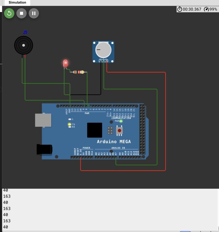
- The log alternates 163 and 40: raw ADC code, then the mapped duty.
- Check: 163 × 255 / 1023 = 40.63 → truncated to 40. This proves the mapping is integer
map(). - 163 counts × 4.9 mV ≈ 0.80 V on the wiper, about 16 % of the knob’s travel.
- The LED in the screenshot is partly lit: about 40/255 ≈ 16 % duty.
Part 3: ultrasonic distance threshold
The sensor converts distance into time: after a 10 µs TRIG pulse it emits eight 40 kHz cycles and holds ECHO HIGH until the echo returns. Distance = speed of sound × time / 2, since the sound travels out and back. At about 20 °C sound covers 343 m/s = 0.0343 cm/µs.
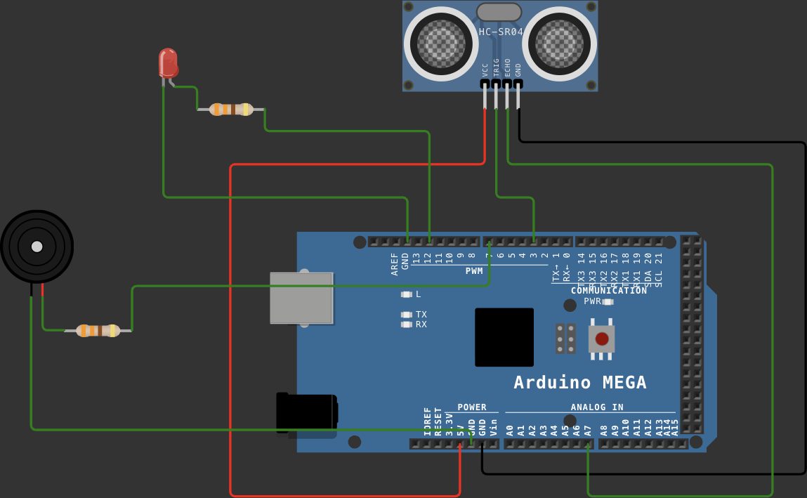
- HC-SR04 pins left to right: VCC (red, to 5 V), TRIG (to pin 3), ECHO (to A7), GND (black).
- LED via resistor to pin 12, buzzer via resistor to pin 7.
- ECHO goes to an analog pin used as a digital input; the code never calls
analogRead()on it.
Part 3: ultrasonic alert
int ledPin = 12;int trigPin = 3;int echoPin = A7;int buzzPin = 7;int duration;int distance; void setup() { // put your setup code here, to run once: Serial.begin(9600); Serial.println("Hello"); pinMode(trigPin, OUTPUT); pinMode(echoPin, INPUT); pinMode(ledPin, OUTPUT);} void loop() { // put your main code here, to run repeatedly: digitalWrite(trigPin, LOW); delayMicroseconds(2); digitalWrite(trigPin, HIGH); delayMicroseconds(10); digitalWrite(trigPin, LOW); delayMicroseconds(2); duration = pulseIn(echoPin, HIGH); distance = duration / 2 * 0.0343; Serial.println(distance); if (distance <= 200) { digitalWrite(ledPin, HIGH); digitalWrite(buzzPin, HIGH); delay(1000); } else { digitalWrite(ledPin, LOW); digitalWrite(buzzPin, LOW); delay(1000); }}- Lines 1 to 4Pin map: two outputs, the trigger output, and the echo input.
- Lines 5 to 616-bit
inton AVR: −32768 to 32767. Relevant to the overflow limit below. - Lines 13 to 15TRIG out, ECHO in, LED out. buzzPin is never set to OUTPUT; see Limits.
- Lines 20 to 21Ensure a clean LOW so the next edge is a proper rising edge.
- Lines 22 to 23The 10 µs trigger pulse the datasheet requires.
- Line 27Blocks until ECHO rises, then times how long it stays HIGH, in µs. Returns 0 if nothing arrives within the default 1 s timeout.
- Line 29Integer division first, then a float multiply, then truncation into
int. 10620 µs → 5310 → 182.13 → 182 cm. - Line 30Report every reading.
- Lines 32 to 35Within 200 cm: both outputs HIGH, wait 1 s.
- Lines 37 to 39Otherwise both LOW, wait 1 s. So the system samples at about 1 Hz.
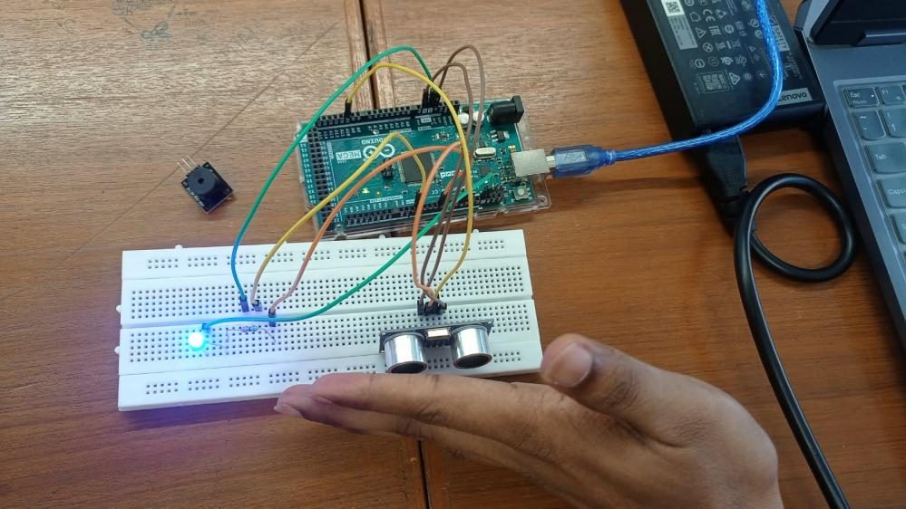
- A hand in front of the sensor; the LED on the breadboard is lit.
- Proves the threshold path: distance under 200 cm → LED HIGH.
Limits and redesign
- No hysteresis: an object sitting near 200 cm makes the alert flicker. Use two thresholds (on below 190, off above 210).
- One reading decides: a single bad echo triggers the alarm. Take the median of 3 to 5 readings and ignore 0.
- Temperature: 0.0343 assumes about 20 °C; speed of sound is roughly 331 + 0.6 × T m/s.
- Blocking:
pulseIn()plusdelay(1000)means the board can do nothing else. An interrupt-driven echo timer andmillis()scheduling remove both.
Say this in the viva
Viva questions
Why
Why divide the echo time by 2?
ECHO stays HIGH for the round trip: to the object and back. Distance is one way.
Why does map() give 40 for 163 and not 41?
It uses integer arithmetic: 163 × 255 / 1023 = 40.63, and the fraction is truncated.
Why are pins 7 and 9 used in Part 2?
They are PWM-capable on the MEGA; analogWrite() only produces a variable duty on PWM pins.
Why an active buzzer in this experiment?
It only needs on/off, and an active buzzer makes sound from DC without any timing code.
What if
What if the object is 5 m away?
Beyond the sensor’s range: weak or no echo, pulseIn() may return 0 (prints 0 cm, which the code treats as “within 200”, a false alarm) or an unreliable value.
What if you write analogWrite() to pin 8?
Pin 8 is PWM on the MEGA (pins 2 to 13 are), so it works there. On an UNO, pin 8 is not PWM and would only go fully on or off.
What if the room is at 40 °C?
Sound travels faster (about 355 m/s), so the true distance is slightly larger than the reading; the code reads about 3 % short.
Design
How would you make this a parking sensor?
Lower threshold (20 to 50 cm), several distance bands with faster beeping as it gets closer, median filtering, and non-blocking timing so beeps and measurements interleave.
How would you measure distance without blocking?
Attach a pin-change interrupt to ECHO, record micros() on the rising and falling edges, and compute the distance in loop() when a new measurement is ready.