Experiment 3: servo motor, relay and the siren design
Two actuator problems a designer meets constantly: “move to an exact position and stay there” (servo) and “let a small logic signal switch a different circuit safely” (relay). Plus the siren, which in your file is a design described in words.
Objective
- Servo
- Command an SG90 to 90°, 180° and 0° in a repeating sequence, one second apart, from an ESP32.
- Relay
- Switch an LED, wired as a separate load, on and off every second through a relay module.
- Siren
- Design a police siren: two alternating tones on a buzzer with red and blue lights alternating in step.
- Learn
- open-loop vs closed-loop actuation, PWM as a command signal, why loads need drivers, and electrical isolation.
System
Design decisions
A servo, not a plain DC motor
- Why
- The task is “go to an angle and hold it”. A servo closes the loop internally: a potentiometer on the output shaft feeds back the actual angle, and its controller drives the motor until it matches the command. The microcontroller only sends the target.
- Alternative
- DC motor (just spins; position needs an encoder and your own control loop) or a stepper (moves in exact steps open-loop, holds with current).
- Switch when
- Continuous rotation: DC motor. Precise repeatable positions without feedback, many turns: stepper.
ESP32Servo library
- Why
- The standard
Servo.huses AVR timers that the ESP32 does not have. ESP32Servo drives the ESP32’s LEDC PWM hardware behind the sameattach()/write()API. - Alternative
- Configure LEDC directly: 50 Hz, e.g. 16-bit resolution, duty computed from the pulse width.
- Switch when
- When you need custom pulse limits or many servos with precise timing.
Servo powered from 5 V, signal from 3.3 V GPIO
- Why
- The SG90 motor needs 5 V; its signal input accepts a 3.3 V logic pulse. One small unloaded servo is within what USB 5 V can supply.
- Alternative
- A separate 5 V supply with grounds joined.
- Switch when
- More than one servo, or any load on the horn: stall current can reach hundreds of mA and brown out the ESP32.
Relay module, not a bare relay
- Why
- A coil needs tens of mA at 5 V and produces a reverse voltage spike when switched off. The module has a transistor to drive the coil and a flyback diode to absorb the spike, so a GPIO can drive its IN pin directly.
- Alternative
- A transistor or MOSFET switching the load directly; a solid-state relay.
- Switch when
- MOSFET for DC loads and fast or frequent switching (PWM). SSR for silent AC switching. Mechanical relay when you need isolation and any AC/DC load at low switching rates.
Load on COM and NO
- Why
- NO (normally open) means the load is off when the coil is unpowered, including when the board is off or resetting. That is the safe default.
- Alternative
- COM and NC: load on by default, off when energised.
- Switch when
- Use NC when the load must stay on if the controller dies (for example a fail-safe lock that must stay powered).
Passive buzzer for the siren
- Why
- A siren needs two pitches. A passive buzzer plays whatever frequency you generate with
tone(); an active one has a fixed pitch. - Alternative
- A small speaker with a transistor driver for more volume.
- Switch when
- Loudness matters.
What we did
Installed the ESP32 board package and the ESP32Servo library.
The ESP32 is not an AVR board: it needs its own compiler, core and a servo library that targets its PWM hardware.
Wired the servo: brown to GND, red to 5 V, orange signal to GPIO 32.
Power and ground for the motor, and one control line. Reversing red and brown damages the servo.
Uploaded the servo sketch; opened the Serial Monitor at 115200.
115200 is the ESP32 convention and matches its boot log, so both show cleanly.
Observed 90° → 180° → 0° each second, and pushed the horn gently.
Resistance to a push shows the internal feedback loop is holding position.
Wired the relay module: VCC 5 V, GND, IN to GPIO 25; load: 5 V to COM, NO to LED via 220 Ω, LED to GND.
Control side and load side are wired as two separate circuits; the contact closes the load circuit.
Uploaded the relay sketch; listened for the click and watched the LED.
The click is the armature moving; the LED proves the contact closes the load circuit.
Servo: principle, circuit, code
Command signal: a pulse every 20 ms (50 Hz). Only the pulse width carries information. The SG90 datasheet gives roughly 1 ms to 2 ms; ESP32Servo by default maps 0° to 180° onto 544 µs to 2400 µs (the classic Arduino Servo range). write(angle) computes 544 + angle × (2400 − 544) / 180.
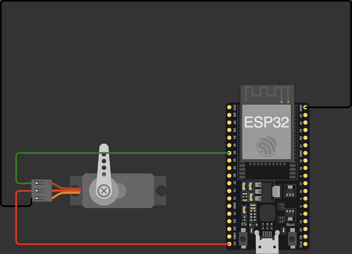
- The servo’s three-wire plug: brown (GND, black wire to the ESP32 GND), red (5 V, red wire to the 5 V pin), orange (signal, green wire to GPIO 32).
- No other parts: the servo contains its own motor driver.
Servo sweep on ESP32
#include <ESP32Servo.h> Servo myServo;int servoPin = 32; void setup() { Serial.begin(115200); Serial.println("Hello, ESP32!"); myServo.attach(servoPin);} void loop() { myServo.write(90); delay(1000); myServo.write(180); delay(1000); myServo.write(0); delay(1000);}- Line 1Servo API on top of the ESP32’s LEDC PWM.
- Line 3Object holding the pin, channel and pulse limits.
- Line 4Any output-capable GPIO works; 32 is free of boot-strapping duties.
- Lines 7 to 8Banner after the ESP32’s own boot log.
- Line 10Allocates a PWM channel at 50 Hz on GPIO 32 and starts the pulse train. From here the hardware repeats the pulse on its own; the CPU only changes its width.
- Lines 14 to 15Set width ≈ 1472 µs and wait.
write()returns at once; the delay is what gives the servo time to physically move (an SG90 needs roughly 0.1 s per 60° unloaded). - Lines 17 to 18≈ 2400 µs.
- Lines 20 to 21≈ 544 µs. Then the loop repeats.
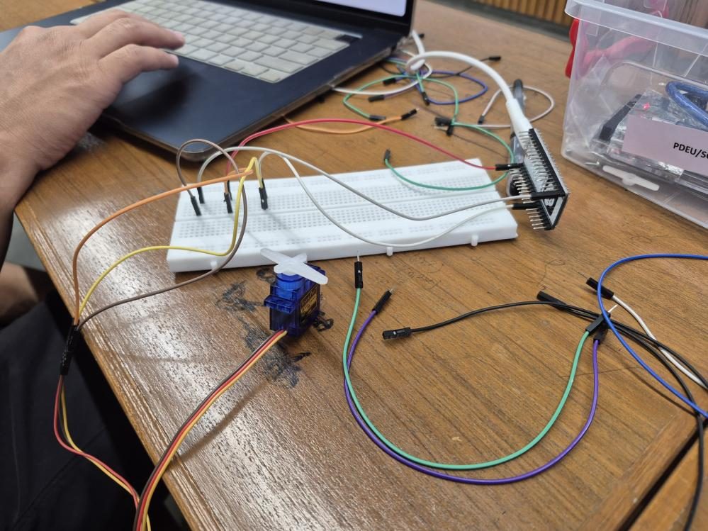
- The SG90 on the bench wired by jumper leads to the ESP32 on the breadboard.
- The horn position in a photo is one moment of the sweep; motion is confirmed by observation, not by the still.
Relay: principle, circuit, code
That separation is galvanic isolation: the 3.3 V logic and the load can be at completely different voltages, even mains, with no electrical path between them. The price: the relay is mechanical, so it is slow (milliseconds), audible, and its contacts wear out after a finite number of operations.
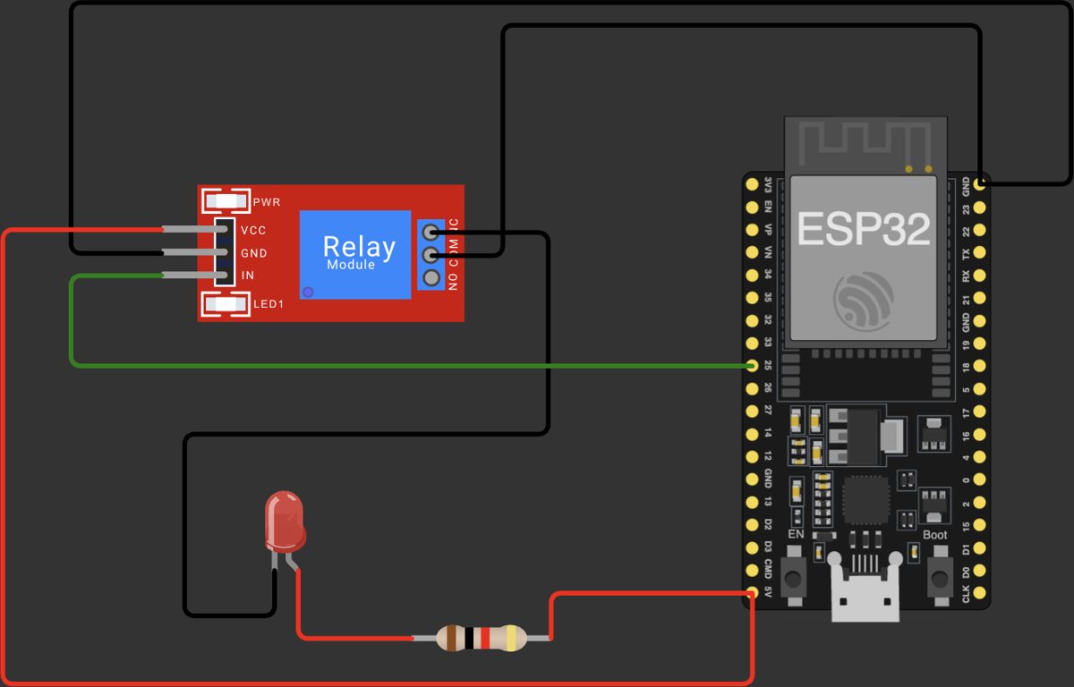
- Module control pins: VCC to 5 V, GND, IN to GPIO 25 (green wire).
- Load side: the red wire feeds COM from 5 V; NO goes through the resistor to the LED, LED to GND.
- Trace the load loop: 5 V → COM → (contact) → NO → resistor → LED → GND. The loop is open until the coil pulls the contact.
Relay switching an LED
int relayPin = 25; void setup() { Serial.begin(115200); Serial.println("Hello, ESP32!"); pinMode(relayPin, OUTPUT);} void loop() { digitalWrite(relayPin, HIGH); delay(1000); digitalWrite(relayPin, LOW); delay(1000);}- Line 1Module IN on GPIO 25.
- Line 7The pin drives the module’s input stage, not the coil directly.
- Lines 11 to 12HIGH energises this module (active-high): COM connects to NO, LED on, click.
- Lines 14 to 15LOW releases: spring returns COM to NC, LED off. The flyback diode absorbs the coil’s spike at this moment.
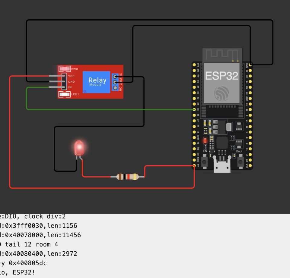
- The LED is lit while the relay is energised: the contact has closed the load circuit.
- The serial pane shows the ESP32 boot log (load addresses, entry point) followed by
Hello, ESP32!: proof the sketch started after reset.
The siren design
In your file the siren is a design: a passive buzzer, a red LED and a blue LED (each with 220 Ω) on three digital pins, common ground. Behaviour: low tone (about 440 Hz) with red on for 0.5 s, then high tone (about 880 Hz) with blue on for 0.5 s, repeated.
- It is a two-state machine driven by time: state A (red, low tone) and state B (blue, high tone), switching every 500 ms.
tone(pin, f)generates a 50 % duty square wave at f Hz using a hardware timer, so the CPU is free while it plays;noTone(pin)stops it.- 880 Hz is exactly double 440 Hz (one octave), so the two states are clearly distinguishable.
- A sweeping “wail” would step the frequency up and down instead of jumping between two values.
Limits and redesign
- Servo power: under load an SG90 can pull enough current to reset the ESP32 via USB. Separate 5 V supply, common ground, and a capacitor across the servo supply.
- Servo speed:
write()jumps instantly; for smooth motion step the angle in small increments with short waits (non-blocking withmillis()). - Relay rate: fine for once a second; for PWM or frequent switching use a MOSFET.
Say this in the viva
Viva questions
Why
Why can’t a GPIO drive a relay coil directly?
The coil needs more current than a pin can supply, and switching it off produces a reverse voltage spike that can destroy the pin. The module’s transistor supplies the current and its flyback diode clamps the spike.
Why is the load on NO and not NC?
So the load is off by default whenever the controller is off, resetting or crashed.
Why does the servo hold its position against a push?
Its internal controller compares the commanded angle with the feedback potentiometer and drives the motor to correct any error.
What if
What if you call write(90) and write(180) with no delay between?
The second command replaces the first before the servo moves: it heads straight to 180°.
What if the relay module is active-low?
HIGH turns it off and LOW on; the LED would be on when the code intends off, and on during boot.
What if you power three servos from the ESP32’s 5 V pin?
Their combined current, especially at stall, can drop the supply and reset the board. Use a separate supply with common ground.
Design
A fan must be switched on above 30 °C. Relay or MOSFET?
For a small DC fan, a logic-level MOSFET: silent, fast, and it allows PWM speed control. For a mains fan, a relay or SSR for isolation.
How would you make a robotic arm joint hold position under load?
A higher-torque servo with its own supply, or a motor with an encoder and your own PID loop if you need more precision than a hobby servo gives.